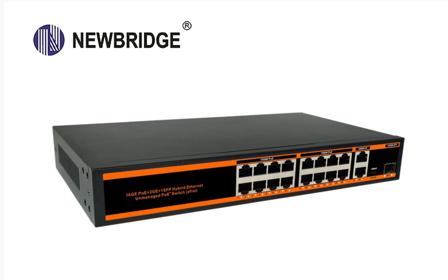
PoE switches can provide power without affecting communication, mainly through the following methods:
Using different wire pairs for transmission
100M network: The standard Category 5 network cable has four pairs of twisted pairs. In a 100M network, 10Base-T and 100Base-T only use two pairs, namely 1, 2, 3, and 6 wire cores for data transmission. PoE power supply allows two usages. One is to use the idle pins 4, 5, 7, and 8 for power supply, where pins 4 and 5 are connected as positive poles and pins 7 and 8 are connected as negative poles. The other is to use the signal line pairs 1, 2, 3, and 6 to transmit data signals and 48V power at the same time. At this time, the DC power supply is added to the midpoint of the transmission transformer. In this way, line pairs 1, 2 and line pairs 3, 6 can be of any polarity, and their power transmission uses a different frequency from the Ethernet data signal, thereby realizing parallel transmission of data and power.
Gigabit network: Gigabit network communication uses the 1/2, 3/6, 4/5, and 7/8 line pairs of the network cable to transmit data. Therefore, for the Gigabit PoE switch, whether it is powered by the data line pair or the idle line pair, all 8-core network cables need to be connected. Taking the data line pair power supply as an example, the voltage and signal frequency of pins 1 and 2, and pins 3 and 6 are divided by the network transformer, and the separated voltage is connected to the bridge rectifier for rectification and power supply.

Follow relevant standard protocols
PoE technology follows standard protocols such as IEEE 802.3af/at/bt, which clearly stipulate key parameters such as power transmission mode, power transmission power, and power transmission distance between PSE devices and PD devices, ensuring the stability and reliability of the PoE power supply system and the coordinated operation between data communication and power transmission.
With detection and control functions
Detection function: The PoE switch will first perform a detection before powering, and output a very small voltage at the port until it detects that the cable terminal is connected to a powered device that supports the corresponding standard, and then it will perform subsequent power supply operations, avoiding the wrong power supply to non-PoE devices and protecting the safety of the equipment.
Classification and power control: After detecting the powered device, the PoE switch will classify the PD device and evaluate the PD The power loss required by the device is calculated, and then the power output is automatically adjusted according to the power demand of the device to provide stable and reliable DC power for the PD device to meet its power consumption without interfering with data communication, ensuring the safety and stable operation of the device.
Special circuit design
Use PoE transformer: The PoE switch couples and separates power and data signals through the PoE transformer, realizing the function of transmitting data and power in the same network cable, and can effectively isolate data signals and power signals to prevent power signals from interfering with data signals, while also ensuring the safety of equipment and personnel.
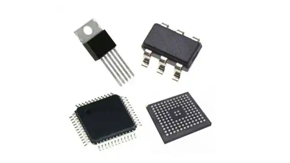
Power management chip: The internal power management chip can accurately control and manage the power supply process to ensure that the output voltage and current are stable and meet the relevant standard requirements. It can also cut off the power supply in time when abnormal conditions occur, such as short circuit, overload, etc., to protect the equipment from damage.
Common power supply schemes for POE switches
End-span method: Data and power are transmitted through the 1236 line sequence of the Ethernet cable, and data signals and DC power are transmitted in parallel on the same pair of wire cores. The transmission frequencies are different to distinguish data and power. This method makes full use of the transmission capacity of the Ethernet cable, reduces the wiring cost and complexity, and is widely used in various network devices that support PoE functions, such as PoE switches, PoE routers, etc. It is suitable for most newly built PoE network environments, and provides data and power support for terminal devices conveniently and quickly.
Mid-span method: Use the idle line pairs in the Ethernet cable that are not occupied by data, that is, the 4578 line sequence to transmit DC power, while the 1236 line sequence is specifically used to transmit data signals. An additional Mid-span device is required, which is usually placed together with the switch. The device has two RJ45 jacks for each port, one connected to the switch with a short line, and the other connected to the remote device. Applicable to the existing network cabling system. Without changing the original network architecture and cabling, the power supply to the PoE terminal equipment can be realized by adding mid-span devices, which provides convenience for network upgrade and expansion.

Adapter power supply scheme:
12V adapter: The 12V voltage needs to be increased to 48V/53V through the boost circuit to power the input of the PSE chip. Applicable to some small POE switches that are more cost-sensitive and have low power requirements.
48V/53V adapter: It can directly provide 48V/53V power supply to the PSE chip, but the buck IC is required to reduce it to 12V, 5V, 3.3V and other voltages to meet the working voltage requirements of different chips and circuits inside the switch. For high-power switches, the voltage is usually reduced to 12V first, and then a high-current buck converter and a 2A/3A buck converter are used to further reduce the voltage.
48V/53V+12V adapter: 48V/53V is used as the input power supply for the PSE chip, and the 12V adapter is reduced to 5V, 3.3V and other voltages through a medium- and low-voltage high-current or low-current buck converter to power other chips and circuits, eliminating the need for a 48V/53V boost or buck converter, simplifying circuit design.
PSE controller chip solution
MP3924 chip solution: This is a 4-port PSE controller compatible with the IEEE802.3af/at protocol. Its integrated VCC power supply can solve the problem of providing 48V to 3.3V power supply for the PSE chip. With a small QFN-32 (5mmx5mm) package, a single-port PSE application only requires one power MOSFET, reducing overall costs. It is highly configurable and provides an I2C interface to monitor the voltage and current of each port. It can also set the current limit of each port. A single port can support up to 40W of power.
MAX5980 chip solution: It is a four-channel power supply controller for power supply equipment (PSE), specially designed for PSE equipment that complies with IEEE 802.3at/af and compatible. The device has detection, classification, current limiting and load disconnection detection functions for the back-end powered equipment, supports fully automatic operation and software programming control, and also supports the new two-event classification and Category 5 detection and classification functions for high-power powered equipment. Each port (category 5 enabled) can provide up to 70W of power while providing high capacitive impedance detection of the original powered device at the back end.
LTC9101/LTC9102/LTC9103 chip solution: LTC9101/LTC9102/LTC9103 is part of the self-isolated PSE controller chipset, based on substrate, designed for PoE2 systems. LTC9101 provides an isolated digital interface to the PSE host, while multiple LTC9102 and/or LTC9103 provide a high-voltage analog Ethernet interface. The LT C9102 provides 12 power channels, each channel powers 2 of the 4 cable pairs in the Ethernet cable, and can power 12 30W ports (each port uses one power channel) to 6 90W ports (each port uses two power channels); the LT C9103 provides 8 power channels, which can be used to power 8 30W ports to 4 90W ports. A single LT C9101 can manage up to 4 LT C9102s and/or LT C9103s, which can be mixed and matched to build a PSE system with different port power combinations to meet the needs of a variety of application scenarios.
